Thanks to the
Dutch Activity Contest I
am
convinced that aircraft scatter
is the best
way to make nice DX contacts on 23 cm.
I
have made in the last few years many QSO's on 23 cm
with Ray GM4CXM using planned aircraft scatter
using aircraft flying through
our
common scatter area. Almost
all our tests were successful.
Mind you, we're talking about
a
distance of 729 km, which for many
2m
station is not possible or a very beautiful DX contact.
In the
past two years I have approximately made fifteen
times a
QSO with GM4CXM using aircraft scatter.
It occasionally failed,
at that
time the aircraft flew exactly
through the scatter
area but there was also good tropo propagation.
Possibly that
a temperature inversion
weakened
our signal
reaching the aircraft or completely
not arriving at the
aircraft.
During the other contests I succeed contacts
at 23cm often
at greater distances.
Usually
I make distances up to about
850 km with
stations from OK, like OK5Z from
JN89ak
about 854 km or with OK1KUO JO80ff about
849 km.
During the
VERON Dag voor de radio amateur I had a live demo in the VHF-cie stand
to demonstrate aircraft scatter.
I was receiving the signal of
the beacon DB0AJA from JN59as,
457 km away, I could show that the signal became much stronger
if a plane flies through the
scatter area.
Since the beacon is not that
far away Troposcatter also played a role
in the reception.
During the demo we many
times saw
an increase
of the signal with more than 20 dB.
Even
more striking is when the distance is
larger.
Without a plane you really copy
nothing
from a DX station,
and if there is a plane in the common
scatter area you will then hear the signal of your
counterpart rise and usually a minute
or two
at usable strength to make a QSO.
Equipment and method
Requirements to be able to
work with aircraft scatter.
Firstly, on both
sides a good working
radio system
and an experienced operator
with the skills to complete a QSO within 30 to 60 seconds.
Depending on
the flight path of the
airplane a
QSO sometimes must be realized in only 30 seconds.
If the flight path is better than
there is more time, up to more
than four minutes.
Planning of a QSO.
Using your own position and the position of the dx station
the scatter point can be calculated.
This can be
done using a tool
built by
SM7LCB, available on the Internet.
In this tool, the own
locator
and the
locator
of the DX station are entered, and the
opening angle of
the two different antennas.
In the figure, you see
the common scatter point
between me and GM4CXM.
|
Now it
is important to know where the aircraft fly, to
determine at what moment the QSO is
possible.
There are a variety
of on-line radars
available that shows where aircraft
are flying.
Beware though of
arbitrarily choosing a on-line radar website,
because most websites are delayed, for safety
and sometimes are
fifteen minutes behind.
That kind of radar is obviously of no use, because using a delayed radar
you
can only see that you could have been able to make a QSO fifteen minutes
ago.
A radar without delay and which I use
myself is:
http://www.flightradar24.com/
With
the use of the radar one can see which aircraft is
approaching the
scatter area and when
a test can begin.
Using a
microwave chat
like ON4KST is
actually
essential, because you want to know if
your DX
station is QRV and at
the right time
and frequency transmitting or listening.
You
agree with each other who at what time and
at what
frequency will transmit and who is going to
listen.
With GM4CXM
most
of the times he
gives CQ in CW and I respond
as soon as I can copy his signals.
This works fine for the tests we
have done up to now.
The
transmitting station gives short periods CQ
or calls the
opposite station for short periods and switches to RX
to listen for
the other station to
return. At the moment that
you copy
the calling
station, you answer
when he
goes on RX, and
you
can then quickly make the QSO
through reports
and locator exchange and finally confirm everything with Rogers and
73's.
The fastest QSO what I made in this way is within twenty seconds.
I sometimes
copy GM4CXM four minutes and can still hear him calling CQ.
In the beginning I was surprised that nobody else in the Netherlands tried a QSO after me,
but if
you look in the scatter maps the area were the reflection arrives
is not that big.
A station more than 30 km away from my home probably cannot hear anything
and the
reflection from the plane which I use to make a QSO will not work for the
other station.
Each amateur must make a calculation, for its own
situation, of the scatter area.
For stations that are within 30 km it should be
possible using the same scatter area to make a QSO a connection to the DX station.
However both
stations should be working fast, because the reflection often
is short.
On my website I have a audio recording of one of the contacts
between me and GM4CXM, who
can be heard for more than 4 minutes
and on the end his SSB
signal comes in calling CQ contest.
During the DAC of June 2012 I made a QSO
scatter on the KLM49J
from Amsterdam to Glasgow,
flying through the scatter point at
more than 11km altitude.
The picture
is made just after the QSO with GM4CXM.
After my first article I started to better understand aircraft
scatter and try to make QSO's with more stations.
One problem that I had trouble was that
the scatter area was not simultaneously
on the radar map.
After some
searching I found a piece of software that both maps placed over each other could be visible
by making the upper map transparent. With this
tool it is much more clear how aircraft in fly the vicinity of a scatter area.
The
program is called Acer GridVista and
be downloaded from
here
After
installing it needs some time to figure out how things work, but that
is reasonably fast to understand.
Now put the map with the calculated scatter area below
the map of the aircraft radar and be sure that both maps have
the same
scale.
If all that
matches
you can click the icon GridVista (almost
top right of your screen) click on the button
transparent.
Then you have to align the two
maps exactly, by using the
mouse on the radar screen and move the map with
the left button of the mouse pressed, gently
moving the map until it fits exactly above the map with the
scatter area.
To align you can use coastlines, or sometimes place names, which often are
placed on same way in the two maps.
It
is a bit trying, but the result is a picture in which you see
the scatter area and the positions of the aircraft.
In this figure
you see a preview.

After
that it is to wait until the moment that an
airplane is approaching the calculated scatter area,
and
then it's time to quickly agree with the other station to start testing
After I projected both maps over each other, I was interested why for some stations
I needed to plan a QSO and why for some other stations this was not or hardly necessary.
I had for several years the experience that a QSO with
OK2KKW actually always works out without planning
- sometimes stronger then a bit less -
.
The explanation I found by looking on the radar maps was simple:
The scatter area needed for that QSO is located in an busy airway
most of the time there were usually two or more aircraft flying
in the
scatter area.
For some other stations the scatter area is way outside an
airway and then you
need to guard
and plan a QSO and keep a look on aircrafts
approaching the scatter
area.
For example the
scatter
area for my QSO with GM4CXM has about
three flights in the evening when the
DAC contest is held.
If you will miss
these planes the chance of making a QSO is
lost.
Once accustomed to this practice, how airplanes
fly and which flights are suitable, it is not very difficult.
So now I know that
very often the
KL49J crosses very
well
the scatter area.
I monitor the
departure of
the KL49J from Schiphol
and then I know that about 30 minutes later,
the flight approaches the scatter
area.
Ten
minutes before
the flight enters the scatter area I chat with GM4CXM
using the ON4KST chat box to warn the him to be alert
for the upcoming possibility.
Then
it's most of the times pretty simple to make the QSO,
in which more than 90% of the cases we tried
actually succeed.
With
SP1JNY from JO73gl a distance of 686 km, I have made 3 times a
planned aircraft scatter test so far which all were successful.
The first time I experienced a QSO with SP1JNY as very special,
because I still remember that my first QSO with SP is
not that long ago needing good tropo propagation.
In using
aircraft scatter
now it is
a
matter of proper planning and good stations on both sides and
to work
methodically,
and then we can always make a QSO
In Figure 4 shows how the plane flew, and
which route it has followed some time after I
the connection
was made.

The diameter
of the
scatter area is user set.
In this picture you can see the plane actually flying
just on the edge of the area.
My
impression is that as the distance between the two stations
is larger also the diameter of the scatter area becomes
larger.
Also I made several
QSO's with GM0USI from
IO75uv
about 722 km, using planned aircraft scatter.
Furthermore, there are many QSO's I made which probably were
successful using aircraft scatter but being unaware,
because
I was not trying to find if an aircraft was flying in the
scatter area.
So
the contacts I made with
OK5Z from JN89ak about 854 km
were made with
great certainty using aircraft scatter.
The
last few months I have been trying to test with
IZ4BER with if we
can make an aircraft scatter
QSO.
In the tree times in
which we now
tested we have not been able to succeed.
Perhaps
this distance is
just too far.
It is
obvious that a large part of the real
DX
contacts on 23cm is made with help of aircraft scatter.
The signals are
usually not
very strong, but success rate is very high.
As
technical parameters of the equipment needed for these contacts
you need to have more than 22 dB antenna gain
and more than 100 watts
output. With a free take off this allows DX
contacts
over 800 km reasonably reliable.
If the DX station has a very nice QTH, for instance many
OK stations
are high up in the mountains,
then the maximum distance
of the DX will be more, because he can
have line of sight contact with a plane over a much larger
distance.
An airplane
flying on
an altitude of more than
10
km is visible over a range of about 400 km away.
If both
stations have a free take of to the horizon and be able to see
the aircraft on a large distance a DX
of more than 800 km is possible.
When one is on a high mountain then he could see the plane even
a
100 km further and the we can make
the 900 km range.
Distances of 1000 km
are not realized using aircraft scatter.
Aircraft
scatter and Doppler shift
During
my demonstration at the VERON DvdA
several questions were asked about
Doppler shift. When we calculate the scatter area we always see
that its located exactly halfway the distance.
If an RF signal is blasted on the
aircraft
the reflected signal will have
a Doppler shift in accordance
with the speed
of the aircraft.
The RX station than receives the shifted signal but
this signal is shifted back just on the same amount as the
signal shift on the aircraft.
During scattering we are dealing with two
Doppler shifts, from the transmitter
to
the aircraft and from the aircraft to the
receiver.
When the
aircrafts flies midway,
the Doppler shift of the transmitter
to the aircraft is just as large as that of the
plane to the receiver.
Because the two shifts are
opposite the net Doppler shift is
zero.
If the aircraft
leaves the center of the path the two
Doppler shifts start to differ, and
the frequency starts to drift away.
But in addition, the
signal strength is usually much less than that the middle of the scatter
area and a
contact is no longer possible.
Occasionally you can indeed hear signals that
encounter Doppler shift, but usually
this
is very short
and useless.
The
height at which the aircraft is flying
of interest.
If the plane flies
low then the signal from
your antenna cannot reach the plane
because the earth
comes
in between. As the
airplane is flying higher the bigger distances can be reached.
On the radar internet site you can
select a
height filter.
For distances up to 500 km
I
usually set the height filter so that I don't see aircraft
flying below
7 km altitude.
For distances above 700 km
I set the filter so that I only see aircraft flying at an altitude of
more than
10 km.
In the November
2012 DAC
I made
a test with GM0USI.
We tested using an
Boeing 747
flying
well
in the scatter area at an altitude of 9 km
height, but that
test failed.
Shortly thereafter
a
Boeing 737 entered the scatter area at 11 km altitude, and
then we were successful in our QSO.
The height of the
aircraft is
certainly important, and one could say
that for
distances above 700 km the
airplane
must be flying above 10 km altitude.
Also
on the other bands, both above and below
23cm, its possible to make aircraft scatter contacts.
Even at 10 GHz
aircraft scatter contacts are
possible, but due to the poorer reflecting
characteristics of the aircraft and the faster
occurrence of a significant Doppler shift
the
distances are generally less than
at 23cm.
Distances up to 600 km at
10 GHz are
certainly possible.
Calculating
aircraft scatter
On the
website of SM6FHZ I found an Excel
spreadsheet to calculate the signal strengths which is helpful
in understanding what to expect.
The
station parameters
data from the two stations as antenna gain,
output power, and so on
must be entered.
Based on radar equations
the spreadsheet calculates
how
strong the signals can be.
I have
been playing with this tool
and
come to the conclusion that this
calculation gives a good impression.
In
practice I have the feeling that the signals are somewhat stronger than
the
spreadsheet calculates,
I estimate a difference up to 10 dB
stronger.
A possible
explanation could be that
the radar equation is based on back scatter,
whereas we are scattering forward.
The determination by
the spreadsheet
of
the reflecting surface of the aircraft
may be an
other source for the difference.
Nevertheless, the spreadsheet gives a good impression
what is possible.
The
starting point for aircraft scatter contacts
must
be a well working technical system with decent
antenna gain
and as much as possible output
power.
Also a free
take off is very important:
you
need to see the aircraft without
obstacles between.
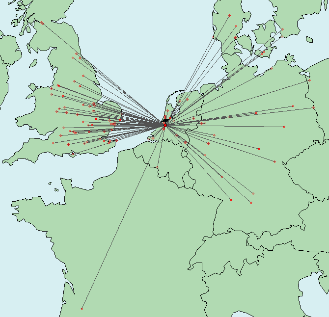
Procedure using in contests
During a contest with high activity with many possible
DX
stations you actually want to have an overview
of the various scatter areas
to see if
aircrafts are
approaching interesting scatter area's.
I use the
again the above-described radar
and the
tool from SM7LCB, but now for a much
larger area.
On the map to calculate the
scatter
areas I enter all interesting
DX
stations with their locator,
and this will then project the
scatter
areas for these stations.
Then
I put the aircraft radar in the same scale
above and I make the radar display transparent.
Provide
the same scale of the maps
and
both maps
neatly aligned you see
all flights
and scatter areas.
When an aircraft approaches
an scatter area
on the map, then
quickly
using ON4KST make a sked request to the
related DX station and agree on
timing and frequency.
Than
it is
a matter of good operating
technique and listening to be able to make a QSO.
The mechanism aircraft scatter is very interesting
to use
and one can further investigate using this technique.

I
myself, was a year or two ago, not
very
convinced of the possibilities, but since
I
have been trying and studied further into this,
I am more and more convinced that
using aircraft scatter brings us
the DX
opportunities at the
higher frequencies
sometimes even better than on the two meter band.
It is interesting to further investigate and study the size of the scatter
area.
As stated above, I think that
the area is smaller
when the DX distance is smaller.
It is
also interesting to examine how the
scatter area must be defined for the
higher frequencies.
Obviously also nice too study
the
relationship between the signal strength of the echo
compared to the airplane type.
The most experience I
have is
with
the usual Boeing 737, simply because
the most aircraft flying are 737's,
but probably
signal strengths and perhaps the
DX
maximum attainable will increase with larger
aircraft such as the Boeing 747 or the modern
Dreamliner.
It is
fortunate that the passengers in the
aircraft
do not know we use their plane to realize a DX contact.
Airscout
Recently I found a new tool for aircraft scatter prediction
build by DL2ALF
This tool shows directly the planes in the map with the
scatterpoint prediction and works more easily than the combined
picture as described above.
Disadvantage from this tool is that it does not show the ideal
scatter area and gives the impression that the scatter area is
much bigger than the SM7LCB tool
After using this tool I have good experience as long as you only
use aircraft within an area of 30 to 40 km to the midpoint.
Although this tool is easy to use I sometimes miss airplanes in
this tool which are visible in the flightradar24 picture.
Also with this tool it's not possible to take an overview and
guard a large area with different scatter area's.
So with this tool you have to choose the qso partner before you
can see the scatterpoint and aircraft around it.
Each tool has it's own advantages and disadvantages.
I have been working with Airscout for a few times and I would
recommend this for operators with little computer experience.
If you don't have problems with using gridvista I think the
SM7LCB tool combined with the flightradar using gridvista is
better
because it presents the scatter area's as a circle around midpoint and it
gives you the possibility
to have an overview of all your dx stations and their scatter
areas.
Airscout can be downloaded at:
http://www.dl0gth.de/software/airscout.zip
Direct link to the website of Airscout:
www.airscout.eu

Other websites about Aircraft scatter:
www.qsl.net/g0iswair.htm