adapted from
the essay from
DJ7FJ
Josef Fehrenbach:
What's different on 10 GHz
EME
to
What's different on 47 GHz EME
by PA0EHG
1. Introduction
The differences
on 47 GHz EME, compared with the well known conditions using 2m or 70 EME are pointed out
in this essay.
On 47 GHz EME earth atmosphere is also in important factor due to attenuation in
the atmosphere. Effects for higher temperature and humidity causing extra
attenuation and therefore the elevation used is an important element in working
47 GHz EME.
There are severaol effects of the very small beamwidth and the change in characteristic of
reflection at the moon.
Also, the received moon noise causes a reduction of sensitivity in the receiver.
2. Path loss -
RADAR equation
Usually, the path loss is calculated using the RADAR equation. It is given by:Pr =(s.Pt.Gt.Gr.l²)/((4.p)^3.d^4) Pr :received power
Pt :transmitted power
Gt :gain of the transmitter antenna
Gr:gain of the receiver antenna l :free space wave, length
d :distance between
transmitter/receiver and target s :cross section of the target
In this basic
form of the RADAR equation, the following units have to be used:
- power in 'Watt' or 'mWatt'
- antenna gain in absolut terms
- wavelength and distance both in the same unit e.g. 'm'
- cross section in m²,
The effective
cross section a of a target is defined in the unit of an area.
Using a sphere with a well conducting surface and a circumference of more than 10l,
it can be calculated as:s = r².p = d².(p/4)
If the surface of the sphere is only poor or non conducting, e.g. the
moon, the cross section has to be multiplied with a corresponding reflection coefficient.
The effective
cross section of the moon can therefore be calculated as:
- diameter= 3.500.000
m
- reflection coefficient =6.5%
= 0.065
s = (3.5.10^6m)².(p/4).0,065 = 6,25.10^11 m²
So, the moon
has the same characteristic of reflection as a well conducting sphere with a cross section
of 6,25. 10^11m² If the target
isn't a sphere, equivalent values for s
have to be measured or calculated.
For practical use, in dB, the RADAR equation can also be written as:
Pr = P(t) +
G(t) + G(r) + 10 log s (m²) - 20 log f (MHz) - 40 log d (km) - 103,4
Calculating the
path loss instead of the received power, the values P(t) and the antenna gains G(t) and
G(r) have, to be fixed to the factor 1, equal to 0 dB.
With the moon, considering an average in distance, the path loss on 47 GHz can be
calculated as 302 dB.
Attention:
The accuracy of the RADAR equation is only sufficient considering the following
conditions:
a) The beam of the transmitter/receiver antenna has to cover the target several times.
b) It is not allowed, that the target is formed by combining spreaded single reflectors. On 47 GHz EME, both restricting conditions are
broken.
3. Antenna
beams
Observed from
earth, the moon covers an average cross section of 0.5º
width.
- in perigee with a distance of 356,400 km Þ
33'32"
- in apogee with a distance of 406,700 km Þ
29'14"
On 47 GHz a
dish of 0,2mtr has a 3 dB angle of 2º. Therefore, a 0.8 mtr dish has a 3 dB angle of 1º and a 0.9 mtr
dish only 0.5º.
Larger dishes cover only a section of the moon.
4. Reflectors
On lower
frequencies, e.g. 2 m, usually 50% of the backscattered signal is reflected from a small
central area on the moon.
RADAR echoes on 400 MHz already show, that not only the center, but also the other areas
up to the rim cause a part of the reflection.
With RADAR
echoes in the X-band, this effect is increased
Therefore, on 47 GHz the whole visible area are more or less producing
reflections. Approximately, the moon surface is a combination of a huge, number of single
reflectors. So, the echo is scattered and contains parts with different travel times.
References for this thesis are:
a) RADAR signals
b) Doppler smear on 47 GHz QSO's
5. Doppler and
dopplersmear
The basic
doppler on 47 GHz can be more than 90 kHz. As the doppler can be calculated in advance by
different programs, this shouldn't be a problem. The dopplersmear is a SHF/EHF specific
problem on EME. Containing spectral parts from both sides of the center frequency, the
CW-signal in the RX isn't a clear single tone. It sounds a little bit
similar to rain-scatter signals, although the rain-scatter signals might be from
a rougher type. Using signal processing care has to be taken about the covered bandwidth. As a
reason for the signalsmear, the libration of the moon was assumed several times in
previous applications. The authors opinion is, that the main part of the smear is caused
by the doppler of different moon areas formed by the rotations of the earth below the
moon.
Examples:Conditions: - The test stations are in the northern hemisphere.
- moon in perigee or apogee
-a) the moon is for the test station in
culmination.
There is no variation in distance to the center and the
northern and southern parts of the moon Þ no basic doppler occurs.
Caused by the rotation of the earth, the test station travels to the left rim of the moon
and simultaneously away from the right rim.So,
the left side produces a positive doppler and the right side produces a negative doppler
with identical value.The maximum frequency
shift will be approx. ± 180 Hz.
The spectral distribution isn't exactly known to the author.With wider antenna beams, it is supposed to be a
cos²
function.
- b)The
station works at moonrise or moonset. Here, the normal doppler has it's maximum and the relative
variations in distance to the lateral rims are in a minimum.Therefore, also the dopplersmear has its minimum.
Fig.Nr.3
shows the relations between doppler and pass of the maximum frequency shift by the
dopplersmear.
- c)QSO between stations in North
America and Europe, both located around the same latitude.
Many variations of dopplersmear are possible.If the moon has the same elevation for both
stations, the smear is at minimum.
- d)The test station uses a very big antenna.
e.g. 4.5 m dish (3dB beamwidth ~ 0. 1°)
The test station illuminates only parts of the moon.As the antenna doesn't illuminate zones with a big
relative motion, there is only a little
dopplersmear, also when the moon is in culmination.
0H6DD has already seen this effect (see DUBUS 2/94).He worked with a very big dish during previous
tests and found out, that almost no dopplersmear occurred.
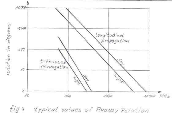
Fig.4 shows typical values of the Faraday-Rotation.
This figure says, that there is no considerable
Faraday-Rotation on 47 GHz.It is therefore
not necessary to work with circular polarisation.Using
linear polarisation, you have to take care about the basic rotation for reflections at the
moon.
The American recommendation, used by most of the active stations, seems to be a usable
compromise.
It is called: - stations in North America work with horizontal polarisation
- stations in Europe work with vertical polarisation
Considering this, the rotation among American stations is kept low, among the European
stations it is even lower.Between America
and Europe there are always approx. 90°.Currently,
47 GHz EME stations only exist in America, Japan and Europe, so you can contact every partner in a
session without any modifications. For optimal performance as
needed on 47 GHz it is advised to adjust polarisation for testing between JA and
W
8. Antenna and feed
On mm
bands the sun and the moon are no longer usable as point sources. When using
large dishes on 47 GHz, larger than 1 meter, the feed cannot be optimized by
simply adjusting for optimal sun noise.
The earth-noise should be minimised by optimising the
antenna.Nevertheless, this part of the ant
-noise will always be 20 to 40K.
The galactic background noise could be ignored, because
it's lower than 1O K.
The
antenna noise temperature on 47 GHz is strongly dependant on antenna
elevation and temperature and humidity.
At low elevation angles (below 25 degrees) the noise from atmospheric losses
is the most important effect for 47 GHz EME
On
47 GHz, the moon-noise, causes the second most important
effect for the sensitivity of the system.It
can be seen as a noise source with a temperature of arround max. 28O K. On one hand this is a positive effect, as you can
use the moon-noise for the tracking of the antenna.On
the other hand, it limits the sensitivity, especially with larger antennas and therefore
the noise factor of the pre-amp gets less important. Probably when using
state of the art low noise amplifiers combined with cooling of the LNA the
moon noise will become a limiting factor in sensitivity. It should be
considered to use the lowest period of moon temperature for EME testing, a
few days after new moon. Moon temperature will be at it's lowest level and
this will bring an advantage of a few tenth of a dB.
As today noise factors of lower than
3 dB are common, the
preamp shouldn't cause any problems. The loss of the RX-feed should be minimised by using
waveguide relays and placing the preamp direct at the feed.
In the graph is shown the great variation in moon temperature during a month
between 208 and 275 Kelvin. This causes a variation in measured moon noise
of almost 0.35 dB.
For a station with a noise figure of 5.7 dB typical moon noise will vary
between 0.45 and 0.6 dB For a station with
a noise figure of 2.5 dB typical moon noise will vary between 1.07 and 1.4
dB
10. Moon tracking
Using programs, e.g. from VK3UM, it is possible to
calculate the azimuth and elevation angle or the declination and rectaszension with a
sufficient accuracy. Nevertheless, it is recommended to control the alignment of the
antenna continuously and check tracking with the moon-noise.Therefore,
a broadband noise-RX in a parallel receiver section can be used.
Modern SDR receivers can assist in this like Spectravue by using the Continuum
mode for monitoring moon noise level
11. Power density in an antenna beam
In order to have a closer look at the reflections on the
moon, it is necessary to analyse the power density in the antenna beam.
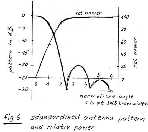
The antenna used in the following tests is a parabolic dish with a standard pattern
characteristic.The first side lobe is 20 dB
down and the second approx. 26 dB.All the
other side lobes are ignored.There is no
difference between E- and H-plane in the radiation pattern.
A numerical method is used to get the power density of the antenna.So it is possible to avoid complicated mathematic
methodes.
Fig.6 shows the radiation pattern and the equivalent
distribution of power density.
Some explanations to this graph:
- The x-axis is the rotation angle.
- Only one half of the pattern is displayed.
- The factor 1 on the x-axis marks the 3 dB point or the half 3dB angle.
- The left y-axis shows values of relative power level of the radiation pattern.
- The right y-axis shows relative values of the transmitted power. They are related to an
illuminated circle area that covers the double angle as
marked on the x-axis, observed
from the antenna source
For example:
How much power is in the antenna beam from the maximum to
all 3 dB points?
Answer:Approx. 55% of the transmitted power.
How much power is in the antenna beam up to the double of
the 3 dB angle?
Answer: Approx. 90% of the transmitted power.
The result for the reception of moon noise shows Fig.7.
The non-linear gradient in this graph is caused by the
radiation pattern of the antenna.
Examples:
How much moon noise is received using a
0.9m dish?
Answer:Approx. 120K.
How much noise is received with a
0.22m dish?
Answer: Approx.10K.
A result of this investigation shows, that the noise
temperature (noise figure) of the RX is not critical, working with a large dish.
12. Relation between antenna beam and received power
In this chapter is only taken care about the absolute
received power.The signal/noise ratio will
be considered in the following chapters.
Fig. 8 shows the connection between antenna size and received power level, assuming a
constant transmitted power.For transmitting
and receiving, the same antenna is used and a dish with 0.88 m in diameter is taken as a
reference.
The diagram shows that with antenna diameters smaller than 0.44 mtr the RX-signal behaves as commonly assumed.At
diameters from 0.44 to 0.88 mtr appears an additional loss of 1.5 dB. The cause for this is the
power density in the radiation pattern as the 3 dB points now approach the moon's rim.
With diameters from 0.88 to 1.2 mtr the signal increases again like it does with smaller
antennas, but a basic loss of 1.5 dB has to be added.
At larger diameters, the curve bends,
and by using dishes of more d= 1.7 mtr, the receiving
level increases not with the double antenna gain.It
increases only with the single amount.
Explanation:
Using small dishes (relative wide antenna beams), only a small part of the beam
illuminates the moon.Considering Fig. 8,
there is an almost linear relation between beam width and power level with antenna sizes.
Is the antenna beam approx. 0.5°, the moon therefore fully covered, the power density on
the moon is direct related to the radiation pattern of the antenna.
With large dishes (narrow beam widths), the beam illuminates only a spot at the moon.So, almost all transmitted power reaches the moon
(as with LASER), only reduced by the loss in the atmosphere.The power reflected by the moon can not be
increased by more antenna gain.The losses of
reflection are assumed to be the same, whether the diameter of the spot is 1000km or
100km.
The reflections on the moon surface are diffuse.When
the same antenna is used for transmitting and receiving always the same moon spot is
illuminated or observed.
Using bigger dishes, the received power increases only with the single gain factor.Now, more gain can only be made on the receiving
side.The moon always reflects the same sum
of energy.If the surface of the receiving
antenna increases, this will have an effect on the power level.
What happens with the received power when stations use
different antennas?
With antennas up to 1.3 m in diameter everything is O.K. If only one partner
uses a bigger antenna (>1.3 mtr), nobody gets a higher RX-signal level.Only
the Doppler smear decreases.
Explanation:
The OM with the relative small antenna illuminates the moon almost completely.The OM with the big antenna only observes a spot
at the moon.If he now increases the antenna,
his receiver level stays almost the same because the observed spot becomes smaller.The reduction in the spot size is compensated by
the bigger antenna size.
This effect is reciprocal. It's also valid when the OM with the big antenna is
transmitting.He only illuminates a spot at
the moon; therefore the OM with the small antenna receives the same power level,
independent from the spot size.
To simplify the calculation of the path loss in such combinations, the gain of the big
antenna can be fixed to the gain of a 6 mtr dish.
If both partners use big antennas, the station with the smaller antenna produces the
limiting factor.To calculate the path loss,
both antennas have to he set to the same size, equal to the dimensions of the small
antenna.
Conclusion:
The effects of big dishes from institutes, e.g. VE3ONT at Algonquin Park, on 'normal'
partners are the same as with dishes of only 1.3 m in diameter.
13.Relation
between antenna size and signal/noise ratio
When the antenna gain will be increased in lower amateur
bands, the signal/noise ratio also increase.This
relation changes, when the moon noise starts to add a contribution to the basic noise that
is worth mentioning.On 47 GHz, system noise
of approx. 200 K looks realistic.It is, e.g., consisted of
180K from the preamp and
the receiver and 30K external noise received by the antenna (earth, feedloss etc.). A
system temperature of 200K seams to be possible without cooling and a temperature of 50K will be lower limit
with cooling the pre amp.
On
47 GHz EME the received noise temperature of the moon
has to be added to the system temperature.Using
47 GHz, the moon has a max noise temperature of approx. 210 K, The received amount of moon
noise depends on the size of the antenna, only big antennas (diameter > 1.3 mtr)
receive the full noise power.The smaller the
antenna, the smaller the amount of noise power that is received.
Considering the antenna beams from chapter 12 the noise
parts can be found in Fig.7.
Tab.1 shows the relations between the antenna
diameter, gain, beam width and the amount of noise received from the moon.
Of course, the received noise from the moon has an influence on the sensitivity of the
system.With a 0.44 mtr dish the
overall noise temperature rises about 40K and a 0.88 mtr dish adds even 120K to the system noise.Some examples have been worked out to have a
closer look at this effect.Therefore, dishes
from 0.44 to 1.7 mtr and system noise (without moon noise) of 50K, 100 K and 150 K are used.
The reflected signals from the moon were related to the according moon noise using a fixed
RX-bandwidth.In order to get an easier look
at the relations, it will be assumed that the partners antenna beam is wider than the moon
and therefore the reflected signals are from the same distribution (room and area) as the
noise signal.
The meaning of the used factors are:
0 dB- In the used bandwidth, the received noise from the moon has the same value as the
reflected power.
3 dB- The
signal power is two times bigger than the noise power of the moon.
6 dB- The
signal has 4 times more power than the moon noise.
10 dB- The signal is
10 times bigger than the moon noise.
Tab 2 and Fig 9 show the effects on the signal/noise ratio
in the correct form (signal + noise)/noise.The
results are really interesting.
It
can be seen at once, that already an antenna diameter of 0.88 mtr is the limit. Bigger antennas don't produce a better signal/noise
ratio. On the other hand, the receiving loss using a 0.44 mtr dish is
relative small.
14. View to the combination of antenna gain, noise, and
power
Working with 20 W, a 0.66 mtr dish and a RX noise figure of 2
dB the own echoes can not be heard. Using
this combination as a reference, the following equipment and its effects are displayed:
Increasing the power is the only effect, that directly
effects the received power of the partner.
Antennas bigger than 0.66 mtr hardly improve the own receiving quality, but
they produce, as long as they are smaller than 1.8 mtr, a bigger
RX-signal for the partner.
Antennas smaller than 0.66 mtr can be useful as receiving, as
long as a very good preamp is used.But the
power should be increased to produce sufficient receiving power at the partner.
Improving the System noise to values lower than
3 dB only
produces a positive effect, when small dishes are used.
Antennas bigger than 1.3 mtr in diameter are not very
useful.The partner with the small antenna receives a signal like
transmitted with a 1.3 mtr dish.The OM with the big antenna doesn't receive a stronger signal as by
using a 1.3 mtr
dish.Only the doppler smear decreases.
An improvement in signal/noise ratio is only made when both partners use dishes
with more than 1.3 mtr, under the condition,
that both illuminate
the same spot at the moon.
16.
Conclusions
Most amateurs at this time use dishes
larger than 1.3 mtr, the beamwidth of these dishes are less than 0,3 degrees
to 0,1 degree
Measuring
moon noise with a large dish will not be influenced, or only very little, by
the distance to the moon. Measuring at Perigee and Apogee will get almost
the same moon noise levels. In both cases the beam hits only a small part of
the moon. The received moon temperetaure remains the same and therefore the
received moon noise will remain the same.
Measuring moon noise with large dishes will
not give any indication on the performance of the used dish
Large dish moon noise level does not tell
anything about gain or efficiency from the dish
Measured moon noise is determined by losses
due to antenna temperature, elevation angle related to atmospheric losses
and overall noise figure of the receiver system used.
Elevation, temperature and humidity are
important factors responsible for large atmospheric losses, best to use high
elevation at least above 20 degrees preferable higher, in early spring time
with low temperatures and low humidity.
Moon
noise varies very strong related to the phase of the moon and the moons
surface temperature
Reflected signals from the moon are not a
sharp beam
For reflections (for QSO's) we need to use
Perigee for minimum loss
Measuring solar noise with large dishes will
not give any indication on the performance of the used dish
For QSO planning the best period will be with
low moon noise, perigee, highest possible elevation on both sides, low
temperature and low humidity and last but for sure not least low spreading
The VK3UM tool is not taking the effects as
mentioned in this paper into account , if we calculate a single way EME contact
between W5LAU and DL7YC we see the calculations as original by VK3UM giving the
following results:
Both stations are in the
calculations at 2.4 mtr dish and atmospheric attenuation is set at 3.6 dB
the received signal is -10.97 dB that is almost 10 dB different from practical
result
Now we reduce antenna gain
conform the model What's different on 47 GHz EME and we get:
Transmit antena gain reduced conform the statement above to 1.3 mtr diameter
Receive antenna gain reduced to 1.7 mtr diameter,
as stated above the gain should be for a 1.2 mtr dish
51.26-1.5 = 49.76 dB
increase from 1.2 mtr to 1.7 mtr lineair increase, for a 1.7
mtr dish 54.28 dB -1.5 = 52.78 dB
increase from 1.7 mtr to 2.4 mtr, increase half of normal
increase, from 1.7 to 2.4 mtr dish is 3 dB increase
so 52.78 +1.5 = 54.28 dB which corresponds to a dish of 1.7
mtr
Moon noise calculated is
very close to real measured values
Sun noise also seems quite close to real measured values, for a good sun noise
calculation the sun flux has to be increased
In this table only look at the results from the home
station
The dish from W5LUA is
reduced to 1.3 mtr dish and the dish from DL7YC to 1.7 mtr, atmospheric
attenuation set to 3.6 dB
received signal is -19.24 dB that is about 1 dB difference between practical
results
The 1 dB difference can be explained by higher atmospheric losses and perhaps
also
the difference between Apogee and Perigee which might not be longer valid when
using dishes larger than 1.3 mtr.
In this table only look at the results from the home
station
In this last calculation I
increased the distance of the moon to Apogee. In this model it is not yet clear if
the difference between Apogee and Perigee should be considered,
it should be confirmed by practical measurements
Up to now this is the
closest calculation I can get giving also good results for moon noise and sun
noise.
For S/N received this is only 0.5 dB different from the measured result.
This last difference probably is caused by uncertainty of atmospheric
attenuation and perhaps also by effectiveness of the used dishes.
17.
Conclusion
This essay shows some differences you have to deal when
moon bouncing on 47 GHz. The conditions on
other EHF-bands are similar but atmospheric circumstances will bring big
differences. Some of the
physical approaches are not in the highest scientific exactitude.But the author is convinced that they are of
sufficient accuracy for practical use.Some
QS0s and noise measurements with the moon prove this.
For 47
GHz EME this means that power output needed should be 20 Watt or more and for
Receive side the dish should be larger than 1.8 mtr or the noise figure in Rx
should be below 2.0 dB and losses between feed and pre amp minimized.
At power
levels of 10 Watt the chance of a successful contact are reduced dramatically or
even impossible. For testing with high elevation levels the atmospheric loss
will be much lower and possible contacts could be possible.