![]()
![]()
|
|
|
This is how my 10 GHz EME station is build.
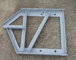
From this part you can find my mechanical solutions I made to get the antenna installed. Difficult part for me was the interface plate between the gearbox and the antenna and how to realize the elevation bearings. EME station setup
For feeding my antenna with the output power from my TWT I am using
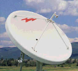
Elliptical waveguide. On the picture below you can see the transmit waveguide in front of the dish.
As I did not have the transitions from the elliptical waveguide to rectangular waveguide I had to build this for myself. Using a 4 mm thick brass plate I made a hole in it to fix it to the waveguide, total loss for 6 mtr waveguide is 0.6 dB. With 150 Watt output from the TWT I still have about 130 Watt at the feed. The 3 cm EME system will be using a 3 meter Andrew dish which is mounted on a radar gearbox on top of a concrete ring. For receive I use a modified Low noise converter from Swedish Microwave. At the feed the DB6NT pre-amplifier is mounted and connected via 3 meter semi rigid cable to the down converter mounted at the back of the dish. The feeder I use is the original Andrew feed but with a self made transition from round to rectangular waveguide. I am still considering to use circular polarization but am searching for the best way to make circular polarization. For transmit I want to use a TWT amplifier capable of more than 200 Watt output which is fed to the antenna by use of a piece of waveguide. Power output at the feed point is about 150 Watt. I have build the auto tracking using Rotorsys as described in DUBUS 3/94. I have modified a Genius mouse so that toe Azimuth and elevation sensor are connected to the mouse. For Azimuth I must have 5572 pulses for 360 degrees and for elevation about 2875 pulses for 90 degrees. The sensors for elevation and azimuth had to be changed in a way that I needed two optical sensors for adaptation to the mouse electronics. The mouse want to know in which direction the antenna is moving. Read here about my antenna readout and Rotorsys usage
On the photo's you can see the sensors for the azimuth and elevation. In this setup I get an azimuth accuracy of about 0.0646 degrees and on elevation 0.0313 degrees. This is well within the limits I wanted it to be. On elevation I still get an error because the sensor is measuring the length of the actuator giving a non linear error. I have calibrated the Rotorsys readout with the commercial elevation sensor I have used before. Up to now I don't have experience with the auto tracking but first indications look well.
I changed the Andrew antenna support in a way that I added a 5 cm thick rod for
the elevation bearings. This rod is fixed to two ham radio bearings from Yeasu. See photo.
At this moment the gearbox and pedestal are installed in my backyard, see photo of this setup. The pedestal is mounted on a concrete ring of 1 meter high so that the dish can be mounted about 2.5 meter over the ground level.
The gearbox is a professional drive for use with a radar antenna. It turns the antenna at 15 rotations per minute which is much to fast for an EME antenna. I removed the motor of this drive for the setup shown in the photo below.
Depending on weather conditions the dish will be installed early next year. For TX I have a TWT amplifier capable of around 150 Watt output on 10368 MHz. This will be installed as close as possible to the antenna giving more than 75 Watt output in the feeder. RX will be a HEMT pre-amp mounted at the feed of the dish.
|